Power
Conditioners
 UPS Industrial Series
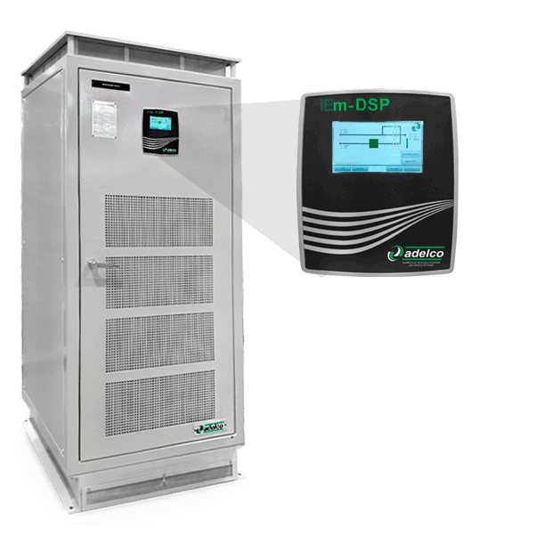
UPSmDSP
UPSmDSP
UPS – Uninterruptible Power System A.C
Uninterrupted power systems A.C are used to supply alternating current power in industrial installations, power generation, transmission and distribution substations and telecommunications systems
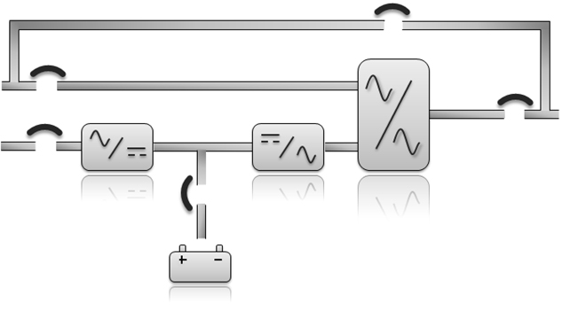
They are equipment based on digital control techniques with state-of-the-art DSP technology, of the “on-line” double conversion type.
Its basic model consists of rectifier bridge (switched or thyristorized, varying according to the power), IGBT inverter bridge with sinusoidal PWM technology (Pulse Width Modulation), bypass circuit with thyristor static switch and battery bank.
The equipment can operate with acid or alkaline batteries, ventilated (open) or regulated by valve (sealed), as long as no voltage value outside the limits for which it was manufactured is not required.
It may also have installed in its alternative branch one voltage stabilizer or transformer adapter.
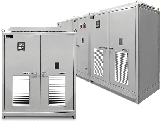
UPSmDSP 50kVA
Characteristics
- Rated Power from 5 to 1,600kVA;
- Double conversion;
- Galvanic isolation;
- SMT/SMD technology boards;
- Redundancy of sources;
- Boost rectifier (IGBT);
- Input power factor ≥ 0.99;
- THDi (selective resonant correction);
- Battery Test with Discharge for network;
- Control with DSP;
- Internal CAN BUS communication;
- THDv (voltage harmonic selective control);
- Linux HMI (4.3”, 7” or 10” touchscreen display);
- Industry 4.0 connectivity;
- Front access for maintenance;
- Redundant ventilation system;
- RS 232-485-Ethernet-USB communication interface;
- Protection degree IP21 to IP55;
- Standards (IEC 62040, N-2760);.
- Other communication protocols or protection degree, under consultation.
System Configuration
- Three-phase/Three-phase;
- Three-Phase/Monophasic;
- Hot-Standby;
- Active redundant parallel or power increase;
- Active and reactive power control;
- Load sharing control;
- Frequency control (fiber optic).
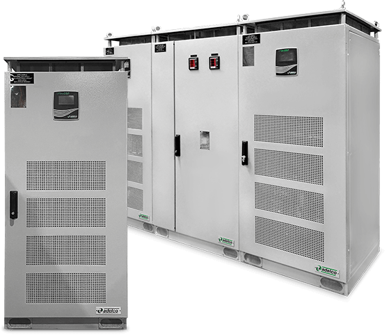
UPSmDSP 20kVA
UPS Corporate Series
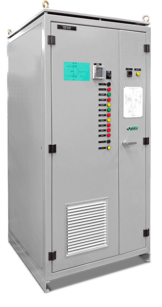
UPSc
UPSc
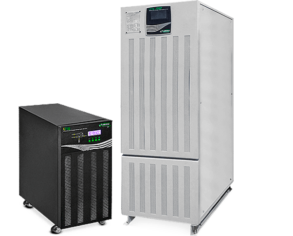
UPS - UNINTERRUPTIBLE POWER SYSTEM IN A.C.
Model Series UPSc 1106 / 1110
- Non-insulated;
- Single-phase;
- Rated Power from 6 to 10 kVA
Model UPScDSP Series 3310 / 3320 / 3330
- With isolation;
- Three-phase or Three-phase/Single-phase;
- Redundant parallelism (optional);
- Rated Power from from 10 to 30 kVA.
General Features of UPSc Models 1106 / 1110 / 3310 / 3320 / 3330 1106 / 1110 / 3310 / 3320 / 3330
- Double conversion;
- Compact and lightweight;
- Automatic bypass;
- Smart battery monitoring system - MMBM;
- Power factor 0.99;
- Discrete IGBT modules;
- Double conversion;
- High input power factor
- Wide input voltage range;
- High reliability and performance;
- Integral protection function;
- Redundancy of sources;
- External SNMP or USB or dry contacts (optional);
- External battery bank (optional);
- Full DSP control;
- Cold start function (DC START);
- Smart fan speed control;
- Advanced battery recharge management;
- Advanced no-master-slave parallelism technology (optional)
- Advanced PFC technology;
- Linux HMI (4.3" touchscreen display);
- SMT/SMD technology boards;
- Intelligent communication port RS-232 and/or RS-485;
- Boost rectifier (IGBT);
- 0.99 power factor;
- Resonant selective correction;
- Battery discharge to mains;
- Control with DSP;
- THDv (voltage harmonic selective control);
- Internal CAN BUS communication;
- Industry 4.0 connectivity.
Applications
- Control room;
- Precision instruments;
- Data centers, hubs;
- Other network devices;
- Commercial Facilities;
- Smart equipment.
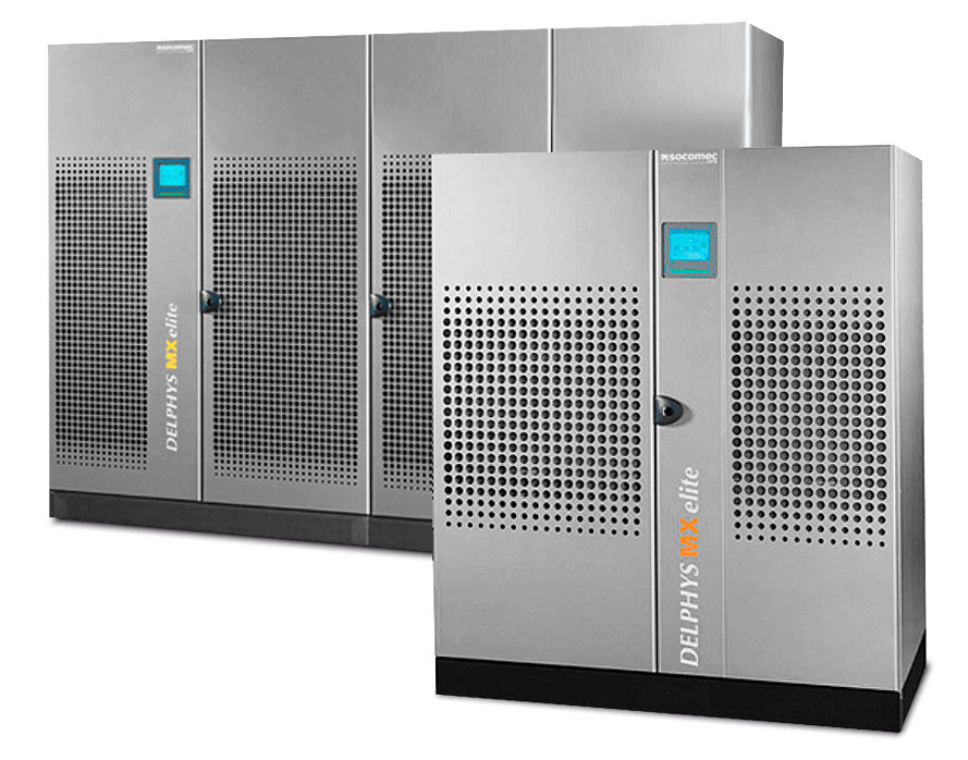
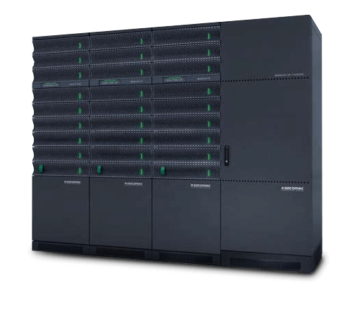
UPS Socomec
A.C. UNINTERRUPTIBLE POWER SYSTEM
It integrates internal redundancy that ensures permanent power even during a system failure and has the highest power density on the market.
Equipment Features
- Rated Power from 250 up to 5400 kVA;
- Protection Degree:
- IP-20 standard;
- Optional IP-31;
- Anti-dust filter;
- Three-Phase Systems;
- Double conversion;
- Parallel system with modular units;
- Effective central bypass for power extension or redundancy;
- Reduced MTTR;
- High reliability and availability;
- Intuitive operation and remote communication;
- Front accessibility;
- THDV < 2%;
- Efficiency of up to 94%;
- Smart battery monitoring system (EBC);
- Compact;
- Standard:
- IEC 62040.
Applications
- Data Center;
- Telecommunications;
- Service sector;
- Networking / IT Infrastructure.
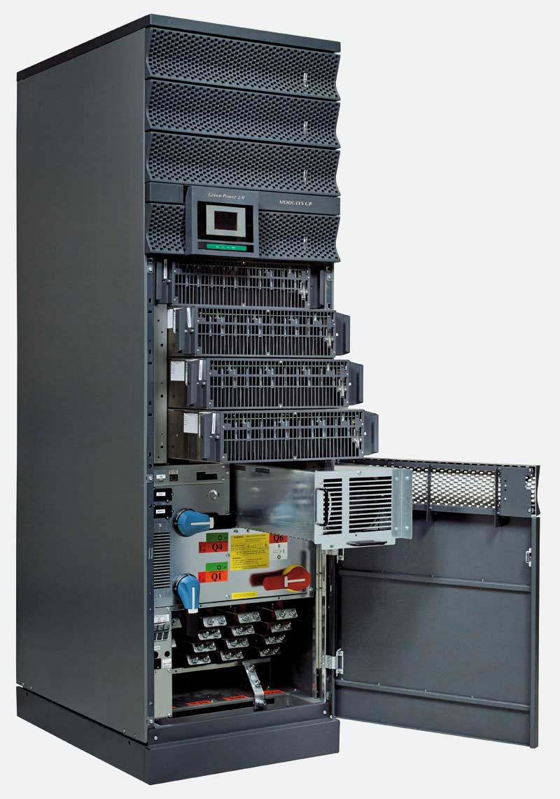
UPS Socomec Modular
A.C. UNINTERRUPTIBLE POWER SYSTEM
With its flexible modularity providing integrated, risk-free power expandability up to 600kVA/600kW, the MODULYS GP range is the ideal solution for unscheduled on-site upgrades or incremental power evolutions. The installed power can be expanded up to 600kVA/600kW by adding 25kVA/25kW hot swap plug-in power modules.
Equipment Features
- Power from 25 to 600kVA;
- Protection Degree:
- IP-20 standard;
- Three-Phase Systems;
- Double Input, Main Network and Auxiliary/Alternative Network
- Double conversion;
- Effective central bypass for power extension or redundancy;
- 25kVA modules;
- Reduced MTTR;
- High reliability and availability;
- Intuitive operation and remote communication;
- 100% front accessibility;
- Input power factor >0.99%;
- Output power factor equal to 1 (as per IEC 62040-3);
- Output voltage distortion < 1% (linear load), < 3% (non-linear load according to lEC 62040-3);
- Efficiency up to 96.5%.
Applications
- Data Center;
- Telecommunications;
- Service sector;
- Networking / IT Infrastructure.
ADELCO IS THE REPRESENTATIVE OF SOCOMEC UPS IN BRAZIL.
For more equipment options go to: www.socomec.com.
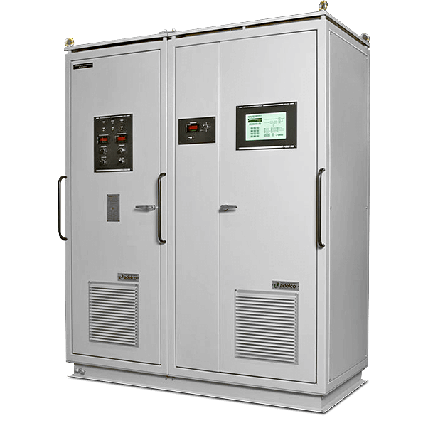
Electronic Stabilizer
EE
EE
Voltage Stabilizer
- Principle - switching leads in booster with serial compensation
- Rated Power;
- 0.5 to 100 kVA - single-phase;
- 1.0 to 400 kVA - three-phase;
- Individual setting per phase, allows 100% unbalancing of charges
- By Pass System insulated and individual per phase;
- Input / output insulation 10 Mohm in 1,500 Vac;
- Complies with IEC 62040-2 standard for electromagnetic immunity, providing protection against interference.
ADELCO stabilizers were developed to power computers, communication systems, industrial controls or related systems.
They are always built with insulating transformer with electrostatic shield. It is a static type equipment for industrial use, which stabilizes the output voltage through the filter combined with an electronic unit, acting as a subtractor circuit of output voltage supplied from the input transformer.
This equipment is assembled in a board with front door, allowing access to all components subject to monitoring or maintenance.
ADELCO electronic stabilizers operation principle is based on electronic switching of a compensation transformer leads. The fact that the switching being done in an ancillary transformer (compensation), not being done directly on the transformer.
With electronic switching, and through main transformer winding currents, the magnetic flow is increased or decreased in the auxiliary transformer.
This switching is performed through a binary combination, achieving 16 adjustment positions.
Inverter DC/AC
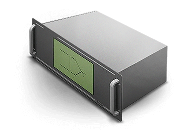
IEm-DSP
IEm-DSP
The uninterruptible power systems in alternating current, IEm-DSP series, are used to supply AC power in industrial facilities, power generation and distribution substations and telecommunication systems.
It is a microprocessed equipment formed by an IGBT inverter bridge with sinusoidal PWM technology (Pulse Width Modulation), by-pass circuit with a thyristor static switch.
It may also have installed in its alternative branch one voltage stabilizer or transformer adapter.
All commands, signals and alarms are available for remote access having as standard the serial interface RS-232, with galvanized insulation and MODBUS RTU communication protocol.
The standard equipment is self-supported manufactured with steel plate profile 12MSG and receiving treatment that meets normal industrial conditions (sheltered and subject to moisture), and can be supplied for installation in aggressive environments with corrosive gases. It can also be built for weather or "off-shore" installations, complying with specific norms.
It also allows the inclusion of options, such as: dry contacts interface for remote signaling, signal transducers, remote controls, among others.
- Powers of;
- 1 to 200 kVA - single-phase;
- 3 to 200 kVA - three-phase;
- Input - 24, 48, 120, 216, 240 or 360 Vcc;
- Parallelism for power increase or redundancy (1+1);
- Microprocessed Control and Supervision;
- RS232/485 serial communication with Modbus RTU or Profibus protocol
- "By - Pass" with static switch;
- AC switchboard incorporated or aggregated;
- Other communication protocols or protection degree, under consultation.
DC/DC converter
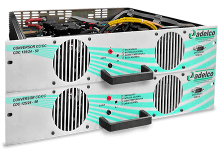
CDP
CDP
The DC/DC CONVERTER provides an isolated and regulated 24 Vdc output voltage from a voltage source in the range of 105 to 160 Vdc. It can supply a maximum current of 30 A continuously at 40°C ambient temperature.
The output of the converter is galvanically isolated from the input source and the chassis, and can therefore be connected as a positive or negative output.
- Polarity reversal;
- 19" rackmountable;
- IN-RUSH" protection;
- HOT-SWAP" connection;
- Overload protection;
- Current limiting;
- Parallelism with current Division.
Static Switch
CHE
CHE
- High reliability;
- Redundant internal sources;
- Remote Access in Real Time and from Anywhere;
- Operational Security and Easy Handling;
- Developed to prevent human failure, easy interaction display, prevention system and signals;
- Flexibility and Adaptability to Various Types of Applications;
- Compatible with any load (linear or non-linear, any power factor and inrush current) and distribution system (single or three-phase, with or without neutral);
- Various communication options (LAN, e-mail, serial, dry contacts, BMS);
- Compact design: Saves up to 40% space;
- Real-time monitoring and maintenance services.
Hot Swap compact system in 19" rack
Modular Static Switch
The solution for alternating current
- Power from 3 to 15kVA;
- In the single-phase voltages of 110, 127 and 220Vac;
- Operation in 50 or 60Hz;
- 19″ modular construction;
- Micro-processed control and supervision;
- RS232/485 serial communication (with Supervision Module);
- Natural ventilation, low maintenance;
- High reliability: MTBF > 500,000h.
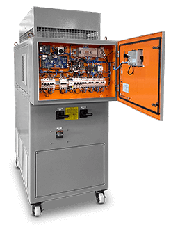
Battery Discharger
The Accumulator Battery Discharger is a system composed by the association of a Direct Current Source, a Switchable Load Resistor Matrix, and the Accumulator Battery elements, whose purpose is performing a discharge test in a controlled and supervised way.
Its configuration allows the control of the discharge process in Accumulator Batteries with voltage range between 2.8 to 28 Volts DC for lead acid or nickel cadmium elements. The discharge current, in constant mode, can be parameterized in the Current Source control, and the Resistor Array automatically selects the necessary load for currents in the 50 to 1000 Amperes D.C. range, with steps of 50 Amperes, in addition to fixed parameterization set points.
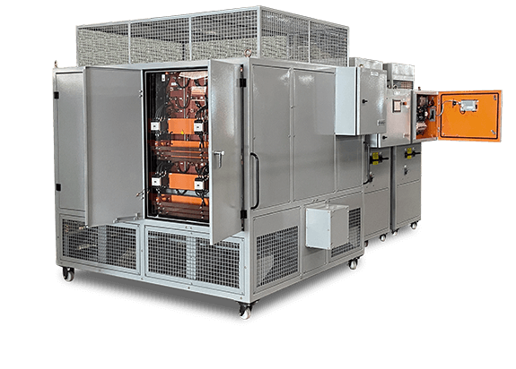
Battery Discharger with Resistor Bank
Battery Discharger with discharge being pushed back into the grid
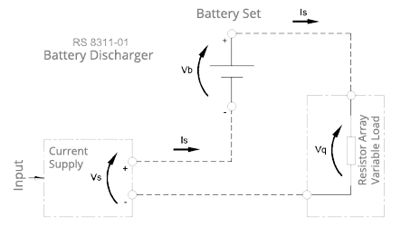
Discharge Process
With Resistor Bank
The Discharger is composed of the Current Source (Is) associated in series with the Accumulator Battery and the Resistor Array with switchable load, as shown in the diagram.
With Grid Discharge
The Battery Discharger with Grid Return allows the converter to inject energy into a specific electrical grid, discharging the battery with direct current according to the values desired by the user.
It also allows the user to graphically follow, through a specific application, the entire discharge of the battery, making an individual or total monitoring of the voltages and currents of the battery set.

Battery Monitoring System
BMS
BMS
Monitor and report the actual operational condition of the Battery Set, through tests in each element/monoblock.
Main Features
- Perfect protection function, provided with voltage alarm, temperature measurement, internal resistance in real time and fault history generation;
- Alarm identification, monitoring voltage, load current and temperature of each battery in real time;
- Communication ports, LAN, RS232 and RS485;
- Module design, easy to install, operate and maintain, features. Isolation between modules. High reliability;
- Excellent analysis of the management integrated treatment that allows consultation of history, curves and data tables, through display in columns;
Application
- Ventilated (open), valve regulated (sealed) and alkaline lead-acid battery systems applied in Data centers, IT Rooms, Industry power supply and off-shore applications.
Measuring method
Our monitoring method is not only measuring the battery's internal resistance, capacity, and other relevant parameters, but the complete monitoring and reporting of the battery's actual needs, and a true reflection of the battery's load capacity and performance.
The test principle of the BMS-ADELCO consists in applying a DC resistance test method, i.e. for each of the elements/monoblocks, a load is installed to measure the change of voltage and current of the battery, and the changed voltage is displayed and compared to the calculated value with the actual value of the internal resistance of the battery .
System Composition: 2V and 12V batteries;
- System Composition: 2V and 12V batteries;
- Operating mode: HMI with LCD display 320 x 240;
- Monitoring: Maximum of 240 cells 2V system = 27 cells 12V system = 24 cells;
- Communication: MODBUS RTU / LAN, RS-232, RS-485.
Battery
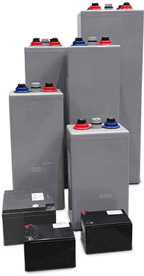
Valve Regulated Lead Acid Batteries (VRLA) AGM or GEL (OPzV)
Stationary valve-regulated lead-acid batteries (VRLA) with electrolyte absorbed in fiberglass blanket (AGM) or gel (OPzV), with nominal voltage of 2V (single elements) and 12V (monoblocs) with nominal capacity of 7Ah/10h up to 3500 Ah/10h.
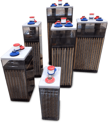
Stationary Lead-Acid Ventilated Batteries (OPzS)
Stationary lead-acid vented batteries with tubular positive plates, with nominal voltage of 2 V (single elements) and nominal capacity of 75Ah/10h to 3500 Ah/10h.
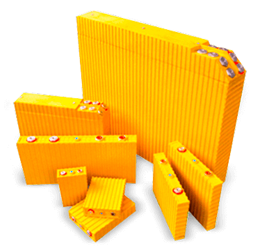
Lithium Batteries
Lithium-Ion Iron Phosphate batteries, with nominal voltage of 3.2 V (single elements) and nominal capacity of 40Ah to 10,000 Ah. Environmentally friendly batteries, as they do not require special requirements for final disposal.
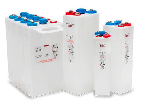
Alkaline Batteries
Stationary nickel-cadmium alkaline batteries, vented or with gas recombination, with nominal voltage of 1.2V and nominal capacity between 7Ah/5h to 1,680Ah/5h.